| The idea of recording trailer dimensions for this Tech Tip came to me after a
trailer was stolen from our club parking lot. Unfortunately for the
owner who had
a very desirable low slung, heavy duty trailer that was perfect for hauling a Bobcat.
Poof, gone! With end of season crane out
scheduled for the
following weekend and old man winter just around the corner, the owner
was frantically looking for measurements to build a cradle to place the boat
on a flat bed
trailer. There was no time to build a new trailer and without the critical hull dimensions it is pretty difficult
to fit one to a new trailer. Then there are those who intend to modify a
used trailer
to fit their boat. Regardless of your situation, you must know where
and how high to place the support bunks to carry your boat securely with the
correct weight on the tongue and over the axle. One of
the easiest techniques is to copy another trailer. Pull up alongside
it and start taking measurements. Easy enough, if one is
available!
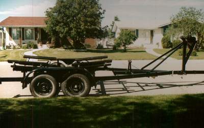
Panache's trailer was manufactured in 1979 by EZ Loader Trailers. The descriptions that follow in this Tech Tip are about this trailer. You should be able to "reverse engineer" these dimensions for another manufacturer trailer without too much difficulty. You should also
read Tech Tip A01, Desirable Features
of an SJ23 Trailer. TRAILER COMPONENTS
 LEGALESE
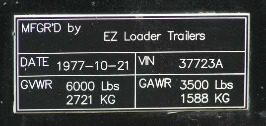
& CAPACITY PLATE - The trailer
capacity plate is shown here. If you cross the 49th parallel, you MUST
have a capacity plate attached to the frame and have proof of ownership in
hand. If you don't own the trailer you better have a
signed and dated letter from the owner (include date, owner address and phone
number) giving the named borrower permission to use trailer registered with VIN# till and end date. In the
body of the letter state where you are going,
the purpose of
the visit and how long you intend to be on the other side of the border. Customs
people can be real picky, so smile when they ask you. TOP LEGALESE
& CAPACITY PLATE - The trailer
capacity plate is shown here. If you cross the 49th parallel, you MUST
have a capacity plate attached to the frame and have proof of ownership in
hand. If you don't own the trailer you better have a
signed and dated letter from the owner (include date, owner address and phone
number) giving the named borrower permission to use trailer registered with VIN# till and end date. In the
body of the letter state where you are going,
the purpose of
the visit and how long you intend to be on the other side of the border. Customs
people can be real picky, so smile when they ask you. TOP
OVERALL WEIGHT - An SJ23 requires a minimum of 2 long fixed support bunks or 4 articulating support bunk boards on the trailer, a keel
support and a V-block or roller on a "winch tree" to pull the hull up on
the trailer and to stop the hull when braking.
Assuming the total weight of an empty SJ23 is 2700 lbs, of which 960
lbs. is ballast, the 4 support bunks must each carry 435 lbs. or each bunk board
870 lbs
and the keel support will hold 960 lbs. Simple enough math
but somewhat difficult to measure with a scale. In addition to this weight you
should allow for about 500 lbs of "stuff" on board,
rigging, rum, gum, scotch, food, beer, a life jacket,
basically all the
staples needed to sustain life! One final point, some SJ23s came out
of the factory heavier than the ~2700
lb. design limit. So heavy that they required a tandem axle trailer.
Yours may be one of them so don't rule this out. TOP
LIGHTS - An SJ23 trailer requires
three types of illuminated lights if it is to be towed on a public road; signal
lights (brakes, left & right), a band of 3 horizontal lights in the center of the frame indicating it is wider than 80", clearance lights to mark the width of the trailer
to passing and opposing vehicles and a licence plate light. I'm not sure if clearance lights are required on the fenders, being the widest part of the trailer. In my experience fender lights take a beating so I use passive reflectors. Regardless, orange in front and
red to the back. See Tech Tip A08 for electrical maintenance. TOP
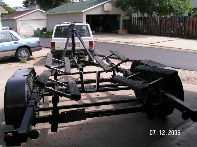 AXLES & SUSPENSION - This EZ Loader frame is made of (3x4)" rectangular steel tubing 1/8" thick with all components bolted together. It was factory equipped with a single 3500 lb. (1588 Kg) straight axle on springs equipped with 10" electric brake drums. When radial tires finally appeared on this continent I installed the
highest load rated tires that could fit the rims, P235x75R15. This
combination can support an empty SJ23 but it is close to its limit. This is
one of the
reasons why I converted the trailer to tandem 3500 lb. axles. See
Tech Tip A04 and A03 for a
description of the conversion. If you want a tandem axle then each
axle should have a GAWR rating of >3500 lbs (1588 Kg), not 2000 lbs. If
a tire blows on a 3500lb. axle then the other axle has a fighting chance to
support all the weight till you stop. Brakes are mandatory with a GVWR
of 6000 lbs. All wheels have drum brakes. AXLES & SUSPENSION - This EZ Loader frame is made of (3x4)" rectangular steel tubing 1/8" thick with all components bolted together. It was factory equipped with a single 3500 lb. (1588 Kg) straight axle on springs equipped with 10" electric brake drums. When radial tires finally appeared on this continent I installed the
highest load rated tires that could fit the rims, P235x75R15. This
combination can support an empty SJ23 but it is close to its limit. This is
one of the
reasons why I converted the trailer to tandem 3500 lb. axles. See
Tech Tip A04 and A03 for a
description of the conversion. If you want a tandem axle then each
axle should have a GAWR rating of >3500 lbs (1588 Kg), not 2000 lbs. If
a tire blows on a 3500lb. axle then the other axle has a fighting chance to
support all the weight till you stop. Brakes are mandatory with a GVWR
of 6000 lbs. All wheels have drum brakes.
The trademark construction of EZ Loader
trailers is to bolt all components
together so it can be adjusted to support
most any shape load and weight. Welding may be cheaper than bolts but you'll
appreciate the bolts if you ever have to adjust anything. This feature
has its price which means you have to inspect the nuts on a regular basis. I
use an old race car technique and applied a dab of silicon sealant between
each nut and the exposed thread. That ended my worry of nuts turning
loose. Checking the trailer annually should be part of your routine
safety inspection. TOP BREAK-AWAY SYSTEM - See Tech Tip A01. TOP
FENDERS - There are two sets of steel straps to support the tops of the
fenders and two more at the bottom of each fender, one at the front and the other at the back.
You can just see a set inside the left fender above. With
four straps supporting each fender they no longer vibrate at highway speed. I
don't allow anyone to step on them, including myself! That's what the aluminum ladder lashed along the
front of the trailer is for. TOP
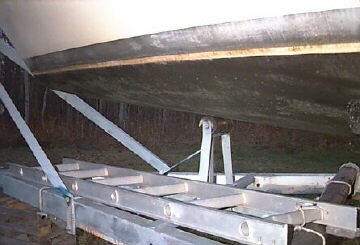
 KEEL
SUPPORT & GUIDES - The combination keel support with keel guides, (1.5x3)" steel tube, is visible across the middle of the trailer above.
The bottom of the keel guide is lined with soft cedar and the sides of the keel guides are lined with slippery UHMW. Since the keel
support bar is adjustable (up/down) with the crank shown at right, I raise the bar up to the keel to support ~600 pounds of it. This offsets some of the weight on the support bunks and the hull. This creates the correct dimensions between the keel support and the hull support bunks. For reference purpose, the bottom of the
keel rests just below the bottom of the trailer frame. KEEL
SUPPORT & GUIDES - The combination keel support with keel guides, (1.5x3)" steel tube, is visible across the middle of the trailer above.
The bottom of the keel guide is lined with soft cedar and the sides of the keel guides are lined with slippery UHMW. Since the keel
support bar is adjustable (up/down) with the crank shown at right, I raise the bar up to the keel to support ~600 pounds of it. This offsets some of the weight on the support bunks and the hull. This creates the correct dimensions between the keel support and the hull support bunks. For reference purpose, the bottom of the
keel rests just below the bottom of the trailer frame.
NOTE - I grease the thread so it is easy to adjust the bar to full height. If I eat my Wheaties in the morning I can
jack the hull up off a bunk to slip cardboard in the gap of a support bunk. I think the original owner of the trailer added this bar. The hand crank is strong but has all the hallmarks of a DIY mechanic. Its a nice feature though. TOP GUIDE POSTS - Guide posts service to direct the floating hull over the trailer so the keel support can grab the keel thereby ensuring the hull is centered on the trailer. See Tech Tip A01. TOP
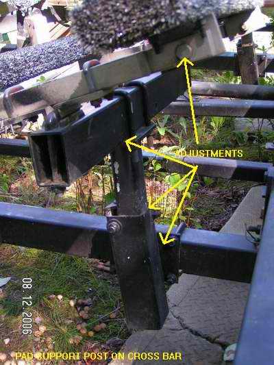
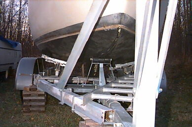
FIXED or ARTICULATING BUNK BOARDS - Panache's EZ Loader Trailer is equipped with four fully articulating support bunks that each consist of two pressure treated (2x4)"s that you can see above. Each bunk can rock left/right on top of its mounting post and each (2x4)" can be rolled independently to fit flat against the hull. Once the (2x4)'s are aligned to the hull I lock them for stability and ease of launching.
There is such a thing as too many adjustments on the launching ramp! This is definitely a time to leave well enough alone. Each pair of posts can rock fore/aft on a common cross bar hinged from the bottom of the side rails. Together the bunks align perfectly to the hull. In addition, each post can be adjusted together or apart to stabilize the hull.
I calculated that the four bunks actually provide more support than two full length 6" bunk boards due to their perfect alignment with full contact. TOP
|
EZ LOADER TRAILER SUPPORT POST PARTS |
- Each support post consists of 2 square telescopic tubes with an internal threaded rod to adjust the height.
- The bottom outer portion of each post is
welded to a 1/4" thick mounting plate, angled about 200
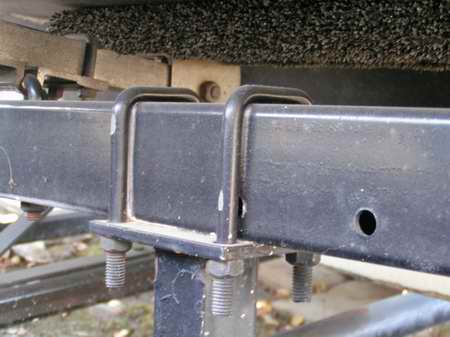
toward the hull to align the forces down the post. The plate is bolted to the cross bar with two U bolts, 2 posts to each bar.
- Two support posts are spaced apart equidistant from center on a cross bar to fit the width of the hull.
- Each inner top portion of the telescopic post is made of 2" square tube with 1/8" thick wall that can be adjusted
up/down and locked inside the bottom outer portion.
- Each of the two 4" square cross bars rotate on end joints, one under
each side rail as shown below in Fig 1. This is how a set of bunks rock fore & aft.
- Each bunk rocks sideways on UHMW bearings shown below in Fig 2. Don't over tighten the bearing or you will crush it. It should be just loose.
- Each (2x4)" bunk rocks on 2 bolt hinges to align to the hull, Fig 2. Lock these bolts once aligned.
- The rotating joints result in bunks that perfectly align to the
hull shape for minimum lbs/in2 loading.
|
Fig 1, Post Pivots - Each trailer cross bar hangs from the rails and pivots from a bolt at each end. The boat is supported by 2 cross bars hanging from these 4 bolts. I lubricate them annually with ATF to prevent rust. 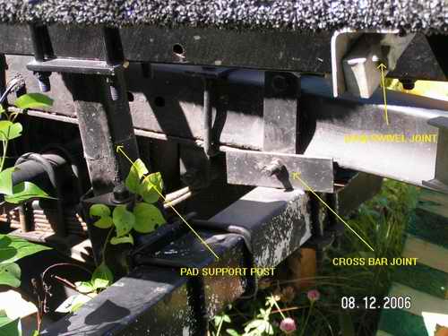
The bunks shown at right rock left right on UHMW bearings. Each bearing is equipped with a stopper to limit outward movement. This biases the bunks inward to meet the hull for a retrieval on the ramp.
|
Fig 2, Support Post -
|
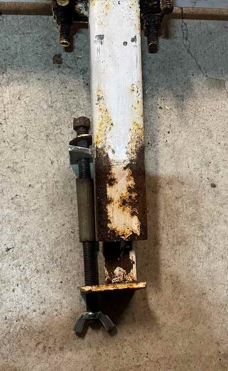
Fig 3, Support Post Height - The post adjusts up/down with the top bolt head and is locked with horizontal locking nuts. I try to keep the vertical threaded rod lubricated with ATF. Never know when one has to be adjusted with the weight of the boat on the bunks. 
|
Fig 4, Support Post -
Support posts adjust apart or together along the cross bar.
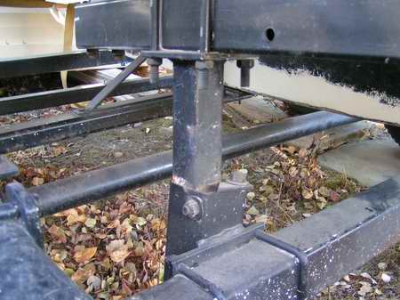 Fig 5, Bunk Cross Bar - Cross bar adjusts (fore/aft) over the bunk post.
|
Fig 6, Bunk Support Post - The photo at right shows the inner workings of the support post, revealing the threaded rod that adjusts the height of the post. The tube over the long bolt limits upward position. Don't remove it. The EZ Loader modified wing nut shown below screws on the threaded rod (Not the standard wing nut shown on the bottom in Fig 7). EZ Loader removes one wing from the nut so the short side points to the inside corner of the outer telescopic post. The remaining wing limits the nut from turning as it is pushed against the inside of the post, regardless of which way the threaded rod is turned. This is the clever trick that pulls the inner tube up from the top, allowing a person to adjust the height of the support post from the top only. By the way, adjusting this post is best done with the weight off the support post. To adjust the post up or down you
first release the horizontal locking nuts. It goes without saying that the thread should stay lubricated.
Robert H. 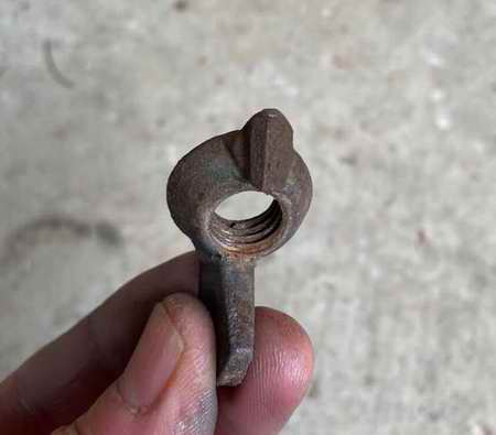
|
Fig 7, Height adjuster - Inner workings exposed.
 |
 TRAILER WINCH
TREE & BOW ROLLER (1999) - I beefed up the original flimsy winch tree because I thought it wasn't rigid
enough to pull the hull up the trailer or support the bow while towing. It wasn't difficult to visualize the boat coming into my "glove compartment" during hard braking. The second reason was to
stiffen the frame for road hauling. I've always wonder about those pathetic winch posts without angle bracing. In reinforcing the tree I replaced the short post with a taller one to raise the winch above the boat trailer eye. This so the boat trailer eye can fit snug under the tree roller.
See
Tech Tip A01. TRAILER WINCH
TREE & BOW ROLLER (1999) - I beefed up the original flimsy winch tree because I thought it wasn't rigid
enough to pull the hull up the trailer or support the bow while towing. It wasn't difficult to visualize the boat coming into my "glove compartment" during hard braking. The second reason was to
stiffen the frame for road hauling. I've always wonder about those pathetic winch posts without angle bracing. In reinforcing the tree I replaced the short post with a taller one to raise the winch above the boat trailer eye. This so the boat trailer eye can fit snug under the tree roller.
See
Tech Tip A01.
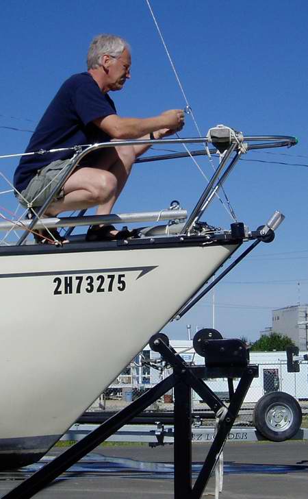
In this photo I'm slipping the jib downhaul ring over the forestay after we stepped the mast. I tend to forget this job at the ramp. This is many years before I added roller furling to Panache. TOP BOW SUPPORT ROLLER (2000) - The 8" wide roller shown
under the bow below works in conjunction with positioning the trailer eye under the roller. It is an important addition I added a few years later. It guarantees perfect fore aft positioning of the hull for every haul out regardless of
the slope of the ramp. See
Tech Tip A01 for a description. It was installed ~6' back from the boat trailer eye. TOP
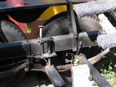
DRAW BAR (1999) - EZ Loader designed this trailer with a single draw bar.
The short overlapping joint that connected the draw bar to the side rails was too weak due to being only 20" long.
Probably adequate for a power boat this trailer could also be used for but
woefully inadequate for the 2700 lbs. of sailboat it now carries. This joint
flexed too much for my liking so I replaced the original 60" long draw bar with a 124" long bar,
creating an overlapping joint of 64". The inboard end of the draw bar is U-bolted to a new cross member of angle iron that is also U-bolted to each side rail. As a result the joint no longer flexes.
About 1.5' forward along the draw bar is another cross member where the new bow support roller was installed (2000).
I was able to install a fixed height roller to fit
the spot because the
rest of the bunks were already adjusted correctly. If the bunks weren't correct the roller height would have been adjustable.
Since the longer draw bar
sticks out ~2' further at the front I can
push the trailer into deeper water without doing the same to the Jeep. I always raised the tailgate of my Jeep Cherokee for visibility on the ramp and now drop the tailgate of my Tacoma. The extra
walking space between both vehicles sure
makes life easier on the loading ramp. It tows more stable at highway speed. TOP
COUPLER - The 2" coupler is not of much interest to this Tech Tip
except that you should be concerned if the coupler is only welded to the
frame. Some welds look pretty but aren't strong. It takes a
trained eye to know the difference. Therefore, it's a good
idea to back up the welds by thru bolting the coupler to the draw bar. The bolts are a good backup to welds that can rust. With the single draw bar configuration of this trailer, the
only benefit an equalizing hitch offers is load distribution of the tongue
weight. While this works well, there is no roll stability since the torsion bars
are parallel to each other. I thought the lack of roll stability might limit the towing
performance but it hasn't. This could be because the maximum speed I tow is 100
K/H (60 M/H)!
MAINTENANCE
 NUTS & BOLTS - All the components on an EZ Loader Trailer are bolted together for easy alignment to different hull shapes. With routine dipping in water the nuts will seize on the thread. This makes it near impossible to twist a nut to adjust the trailer. For this reason I dribble ATF on the thread around each nut. I include the lug nuts on the wheels which is a lesson I learned when helping a guy with a flat tire on the highway. NUTS & BOLTS - All the components on an EZ Loader Trailer are bolted together for easy alignment to different hull shapes. With routine dipping in water the nuts will seize on the thread. This makes it near impossible to twist a nut to adjust the trailer. For this reason I dribble ATF on the thread around each nut. I include the lug nuts on the wheels which is a lesson I learned when helping a guy with a flat tire on the highway. - PAINT - The real reason for a coat of
paint is to prevent rust. The fact that a fresh coat impresses the dock watchers at the ramp is another issue all together. Panache's trailer was painted white from
the factory which was always prone to rust. So I knocked the
rust off, treated the spots with rust converter and painted the trailer black, especially the bottoms of the rails. I chose black Tremclad because the sun heats it very quickly to dry
the metal and prevent rust.
-
I prefer a matt or satin finish because dew drip off quicker. This finish also reflects some light, making it easier to see in the dark than flat paint. I'm gradually painting over the flat paint shown in this photo.
Tremclad must be painted with a brush or sprayed with an airless gun operating at ~50 psi. If the viscosity is too thick then thin it with paint thinner. The thinner is also used to clean the gun at the end of the job. The trailer gets a light coat every 5 years and I've had little rust since.
-
By the way, the ONLY way to
paint a boat trailer is with an airless spray gun as it can get into nooks & crannies that a brush cannot. In addition,
I'll guarantee you at least half a dozen bruises on your shins and cut knuckles if
you use a brush. Don't ask!
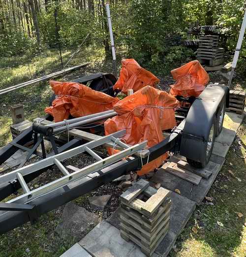
- BUNK BOARDS (2025) - In mid summer I returned to Panache's trailer for some routine maintenance and was surprised that the wood support bunks were damp. Too damp for my liking as this could lead to wood rot. This condition was aggravated by the fact that the trailer is parked in the shade during the summer, facing directly into the prevailing weather. The shade has always been good for the tires though. I returned during a hot spell, knowing the bunks would be dry, and covered them with the 4 small tarps, BBQ style. The bottoms are left open to keep the bunks dry, which they did for the remainder of the summer. The covers look sloppy because the mosquitoes were vicious and I was not about to sacrifice myself to these blood thirty invaders.
- COVER BUNKS WITH RUGS (2025) - See Tech Tip A01 TOP
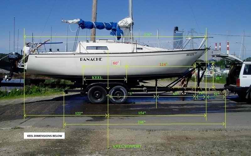
WEIGHT DISTRIBUTION
TRAILER
DIMENSIONS & POSITION of SUPPORT BUNKS for CORRECT WEIGHT DISTRIBUTION.
(A huge debt of gratitude goes to the guys who helped proof read these
dimensions).
HULL FORE/AFT POSITION RELATIVE to the AXLES - To provide adequate hitch weight for stable towing,
position the mid point of the hull (front of the large window) directly over the axle of a single axle trailer
or over the walking bar (between axles) of a tandem axle trailer.
KEEL SUPPORT BAR RELATIVE to the HULL - The keel support bar is
positioned midway between the axles or the front of the large window.
This
is at the maximum girth of the keel which is 7.5" wide.
The boat rests on the trailer with the bottom of the keel flush with the
bottom of the frame.
TRAILER BOW ROLLER RELATIVE
to the BOAT TRAILER EYE - For
easy, quick hassle free ramp launching you want the boat trailer
eye to rest snug UNDER the roller on the tree when the boat is level on the trailer.
Therefore the winch line goes
UNDER the roller. This allows the boat to slide into the
water unimpeded during launch time. (In the 1990s I replaced the
V-block with a roller to reduce wear and friction. See
Tech Tip
B26. I had to build a much taller and beefier tree to raise the winch above the boat trailer eye.) The added advantage is that when the boat trailer eye is resting UNDER
the tree roller, you know the boat is positioned correctly on the trailer.
A very convenient reference mark when retrieving on the ramp. In addition, the trailer tows quieter when the boat is snug up against the winch tree.
The winch must be
placed a few inches above the roller so the hull is pulled up and forward
as it is comes to its final resting spot on the trailer. The
pivot bolt of the winch measures at 41" above the frame. The boat is retrieved by floating it on the trailer as the
winch and boat trailer eye cannot pull 3000+ pounds of weight up the support
bunks. There is too much friction for that much weight. See
Tech Tip B26.
(Measurements shown below are to position the
hull on the trailer)
________________________________________________
IMPORTANT - DO NOT make your trailer to the
exact dimensions
shown below.
I tried to take accurate measurements but since I was measuring on my own, they
are likely off a bit. So allow for adjustments to fit the hardware to your boat.
|
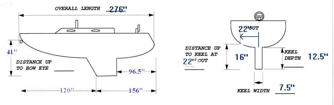
HULL MEASUREMENTS |
|
LOA = 23' |
SUPPORT BUNKS - Distance up to hull @
22" from center line = 16" |
|
Up to Boat Trailer Eye = 41" |
Distance from center line =
22" |
|
Transom to front of Keel = 156" |
Keel Width = 7.5" |
|
Transom to back of Keel = 96.5" |
Keel Depth = 12.5" |
|
Total Hull Weight = 2700 lbs (dry),
~3200 lbs (with gear). |
Stuff Onboard about 500 lbs |
|
Vertical Clearance - 9'
(you need to know this for garage door, under a bridge, etc.) |
The four
support posts on my trailer form a rectangular box that is approximately (48 x 70)"
and 16" deep, relative to the bottom of the keel. The keel
support resides at the bottom of that 16" deep "box".
-
BUNKS FORE/AFT
- The posts, or centers of the bunks, should be about 70" apart (front to back)
so the weight is distributed equally over the front/back bunks.
This is a compromise to support the hull without a keel support. This would make a bunk board about 94" long. This spacing optimally supports
the keel and overhanging ends. Relative to the boat, the center of
the front bunks touch the hull 1 foot aft of the mast
step and the back bunks under the companionway bulkhead. These
proportions work in conjunction with having an adequate support under the 900 lb.
keel so the hull is relieved of having to carry the ballast. Having
adequate support for the keel is very
important for long-term storage and is probably THE best reason to empty
the boat while it's on the trailer.
-
BUNK SPACING
- The posts should be about 44" apart (across the
trailer) so the hull doesn't rock sideways. Any
wider than this and the bunks provide too much lateral support and not
enough lift. The posts could spread apart with the hull crunching down through
the middle.
-
BUNK HEIGHT - The front and back bunks must be approximately 16"
high relative to the bottom of the keel. Leave room to adjust the
height of the bunks.
-
KEEL SUPPORT - The keel support bar must
be just above the top travel of a single axle so it does not stop the
upward travel of the axle. It can be placed between the axles if
you have a tandem axle trailer.
NOTE: Every
towing combination is unique. The
above dimensions are from my trailer and will get you in the "ball
park" for yours. They suit
the hauling requirement of my short wheelbase
Jeep Cherokee equipped with 4L engine and 5 speed. Since I replaced it with a 5 speed automatic Toyota Tacoma, towing is much smoother and easier. To date there are three
copies of my trailer rolling around out there. My trailer tows very stable at 100KM/H (60M/H) and you have absolutely no reason to go faster than that! TOP
ALIGN THE SUPPORT BUNKS - The
simplest method of guaranteeing proper weight distribution is to align the
bunks to the hull, something that cannot be done with the boat off the trailer. Failure to do this correctly will result in
straining the hull around the support bunk and quite likely damage it over
the long term. Note Glen's comments below.
"A frequent failure on an SJ23 are the flimsy, non-structural bulkheads adjacent to
the mast compression post. These bulkheads are mostly a divider between
the V-berth and the settees. This joint often fails after a few big bumps going down the road on a
trailer. Another area that tends to be soft is the centerline of the floor just aft of the keel. This area has no substantial bulkhead to
help stiffen it. Trailering, grounding, or sailing could transfer a
keel load up into the deck or cockpit. Having a boat sit on a trailer with excessive keel loads for a long time in hot summers
allows the boat to essentially melt onto whatever trailer form is beneath
it. All fibreglass boats do this. A repair trick for big dents is to heat
the surface with a heat gun and the tooling memory usually returns the hull to the
original shape. Then you fix the trailer!" Gleno.
- See
Tech Tip B28 for
someone who repaired a dented SJ23.
There are three key factors to align the four bunks or two bunk boards
correctly so the hull weight is distributed equally amongst them.
- BUNK SPACING - If the bunks are too close together
(side to side) the boat will rock sideways at highway speed. If the bunks are
too close together (front to back) then the boat will hobby horse going down the
road. Position any of them too close together and the hull may
roll off the trailer if stopped too hard or angled too much on the launching
ramp. Either situation is wee bit disconcerting, to say the least.
-
BUNK HEIGHT - The support bunks on some trailer are so out of adjustment with respect to the height of
the hull that you have to wonder what damage is being done. When someone reports
this problem it is usually about a vessel that has been neglected
for a "zillion years" in a barn somewhere. The person
usually
adds that there is a definite depression in the area of the rollers and
the hull is pushed in a bit (soft or mushy). The
worst situation is when one of the bunks is higher than the rest. It
holds more weight and pushes harder into the hull. Not good. Conversely if one bunk is lower than the rest, the hull is
inadequately supported in that quadrant. Bunk boards are equally as guilty with this problem.
The source of this problem is somewhat perplexing because if
the hull is symmetrical (left to right) and touching the hull, then why aren't the bunks set to
equal height? Especially since it's fairly easy to adjust the bunks to
the hull when the boat is sitting on the trailer. In fact, this is the
best time to make those minor adjustments, to make her sit just so.
You can resolve this problem by measuring the height of the bunks when the boat is
off the trailer. It will confirm that the bunks are equal height and therefore
supporting equal weight. Mine
looked OK until I measured them, only to discover that both starboard
bunks were 1" lower than the port bunks. No wonder the boat couldn't
sit level when centered on the trailer. This demonstrates how
deceptive this problem can be. Measure, don't assume. Then sometimes I see a hull that
sits so crooked on a trailer that you have to wonder about who loaded
the boat or why this was done. This problem is more associated with the operator
than with the design of the trailer as it is due to poor placement of the
boat on the support
bunks or using bunks without adequate padding. It looks so pitiful and it's such a
shame to abuse a good craft like a San Juan sail boat.
-
BUNK SIZE
- Rollers, while
convenient for launching, are generally too few or too small to
adequately support a fully loaded sail boat. The pounds per square
inch loading on rollers is too high for long term storage. This
is why bunk boards are used for a sailboat. On most trailers the size of the bunks are within the pounds per square
inch rating of the hull. TOP
BOAT OFF TRAILER - I rocked the boat on my trailer after my alignment
described above and wasn't satisfied the bunks were supporting the boat
equally. A quick trip hauling the boat down the highway confirmed this.
I could almost slip my hand between one bunk and the hull. Obviously
the hull was moving on the trailer and not settling well. Something
was out of whack and it is difficult to assess the bunks with the boat on the
trailer.
The following steps
describe how I fine tuned the height of the support bunks after the boat came off the trailer. You can use my
final dimensions in step 5 as a starting point to adjust the bunks on
your trailer. When you measure the height of the support bunks;
-
If the ground
is absolutely flat and level, like an aircraft hanger, you can measure the
height of the trailer frame and each bunk from the ground.
Park the
trailer on smooth level pavement or concrete and measure the frame to
ensure it is parallel to the ground, fore/aft & sideways. This is assuming the frame is not twisted, same size tires all around and all springs are at the same height. If the ground is rough you have to measure the bunks with respect to the top of
the frame. A lot more difficult to do.
-
To confirm that the
trailer frame is straight and on an even plane (not twisted), measure the
distance from the ground to the top of the frame, all around the trailer.
If all measurements are the same, you have a straight frame. It's amazing the
number of twisted trailers out there. Another measurement that could be made is to stretch two strings diagonally
across the frame. If the strings just barely touch at the crossing, you
have a very straight frame. This is an extremely accurate method but it
is difficult to find a couple of clear shots across the trailer for the
strings. It's worth
doing though, if for no other reason than a check.
-
Confirm that the side
rails are parallel (left/right) to each other by measuring the distance between them.
Many single axle trailer frames are not parallel because it is not as critical.
It is absolutely imperative
that the side rails of a tandem axle trailer be parallel.
-
If the trailer frame
is straight and the rails are parallel, you can safely measure the
height of the bunks from a straight edge placed across the frame, which
is now a very accurate reference, or the ground if it is absolutely flat
like a hanger floor.
-
The centre of each support bunk should be
about 19" (+ or - 2") above the bottom of the keel.
 After this initial alignment
followed by another with the boat on the trailer, the hull has never moved
on the bunks as I travel down the road. It just settles in there
and stays. Sure makes for relaxed driving. After this initial alignment
followed by another with the boat on the trailer, the hull has never moved
on the bunks as I travel down the road. It just settles in there
and stays. Sure makes for relaxed driving.
It should be noted that Panache's trailer is equipped with four fully articulating bunks, a
trailer bow support roller, an adjustable keel support bar and a very sturdy roller on the tree. The
dimension of each "bunk"
is (24x42)" and consist of two lengths of pressure treated (2x4)" covered with rug (bottom left open).
The full articulating feature ensures they align perfectly to the hull at all stages of a ramp launch. I can't emphasize enough how important it is that the pads align to the hull. The trailer is extremely stable at highway speed. TOP
Happy Hauling.
|