| SJ23 Tech Tip D12, (Updated 2026-04-27) Bob Schimmel. | |||||||||||||||||||||||
|
Outboard Repairs - 1976 Merc 7.5hp E/W Thunderbolt Ignition. |
|||||||||||||||||||||||
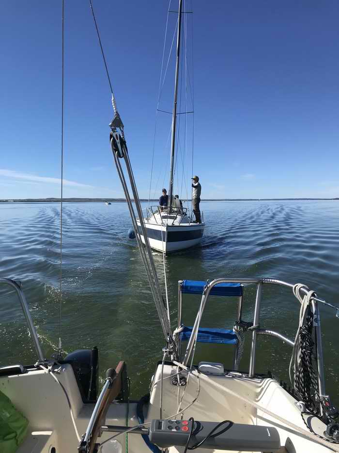
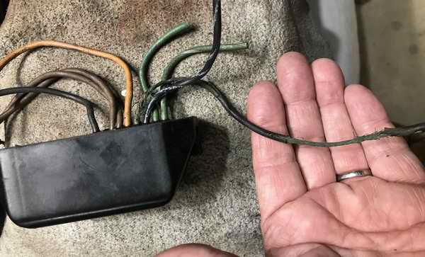 Its a tad disconcerting, to put it mildly, when you discover corroded wires on your trusty outboard. Take a close look at the exposed wire in my hand. The deteriorated brittle insulation has fallen off and the bare wire is deeply corroded with copper oxide. But its at the back of the "Switch Box," where the corrosion is down to two strands. That it is most alarming. The corroded blue wires are for the bottom cylinder. I cut the green wires for the top cylinder to facilitate removal. Its a tad disconcerting, to put it mildly, when you discover corroded wires on your trusty outboard. Take a close look at the exposed wire in my hand. The deteriorated brittle insulation has fallen off and the bare wire is deeply corroded with copper oxide. But its at the back of the "Switch Box," where the corrosion is down to two strands. That it is most alarming. The corroded blue wires are for the bottom cylinder. I cut the green wires for the top cylinder to facilitate removal. The idea of towing a disabled boat while under sail has always appealed to me. But with the urgency of the situation I have always thought it prudent to tow with the control of the outboard and rudder. I have towed a few power boats, much to their chagrin. In 2024 the lake was a mill pond when I was on my trek to the far end of the lake for Panache's end of season haul out. About half way there some guys waved me down. There was zero wind and their outboard was dead. They were actually sculling back to the marina that was still 5 miles (7 KMs) away. Talk about optimistic. So I did the honourable thing and offered them a tow. When I look back on it I'm amazed at how well my 7.5hp Merc pulled their boat, given the few strands left in the corroded wires of the Switch Box. While the main drive of a sailboat are the sails, there are times when the engine is required in a marina, a narrow channel or for the foibles of Mother Nature. I need my outboard working again.
What follows are related repairs. |
|||||||||||||||||||||||
|
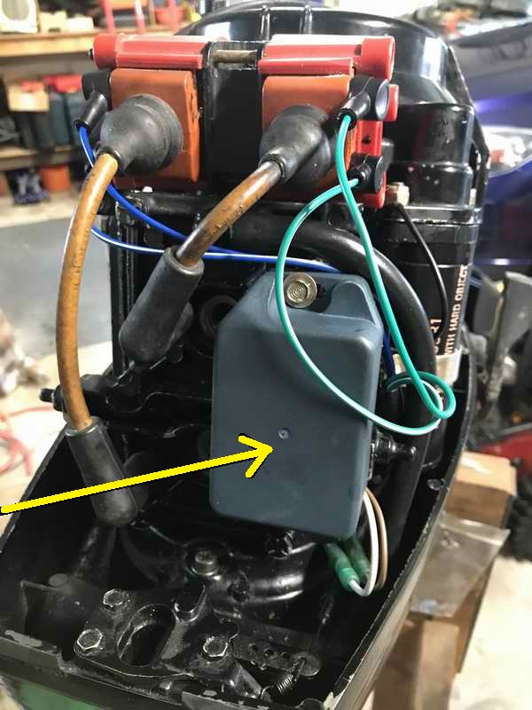
Much to my surprise the 1976 factory Switch Box had badly corroded wires that connected to the ignition coil for the bottom cylinder. Just two strands were left which is too much resistance to create a healthy spark. The brittle insulation fell off as I rubbed the wires to remove a spark plug. Judging by the extensive corrosion on the wires, the insulation was cracked years ago. The local repair shop told me that early vintage Mercury outboards (3-25hp) are noted for this problem. My guess is the insulation finally broke down after years of exposure to oil and high temperature under the engine cowling. Only very special insulation in the 1970s could withstand oil. However, none of the terminations are sealed to the insulation, leaving corrosion to creep under the insulation. This is likely the reason for the fouled bottom spark plug and erratic idle of the last few years. At any rate this condition is not dependable. Now for the bad news. The OEM Merc Switch Box is manufacturer discontinued but my local dealer found the last OEM switch in Vancouver, BC at $600 Ca. A tad rich for me! When he found a slightly cheaper one for $500 I thought this too expense for a 49 year old outboard making it time to replace it, almost! The good news is that I found an after market module for $155 Ca via the good ole Internet. Finally some common sense. It is prudent to take a photo of the factory installed CDI module, noting where the wires are terminated and how they are routed, especially if you do the repair weeks after the replacement CDI arrives. The wires on Panache's new module were not labelled and didn't come with instructions. The BN & WH wires are trigger wires for the top & bottom cylinders. If you match colours each will trigger the correct cylinder. Have faith!
Its quite a job to fit all the components of an outboard within the tight constraints of the case. You have to give the engineers credit for their design. The routing of the 8 wires of this CDI module are no exception. It took a few tries to achieve a layout that prevents chafe or overheating, all with minimal strain. I twisted the wires slightly to lower the impedance and to minimize vibration. The wires are coated with Marine Goop to protect the insulation and the exposed terminals are coated with conductive grease.
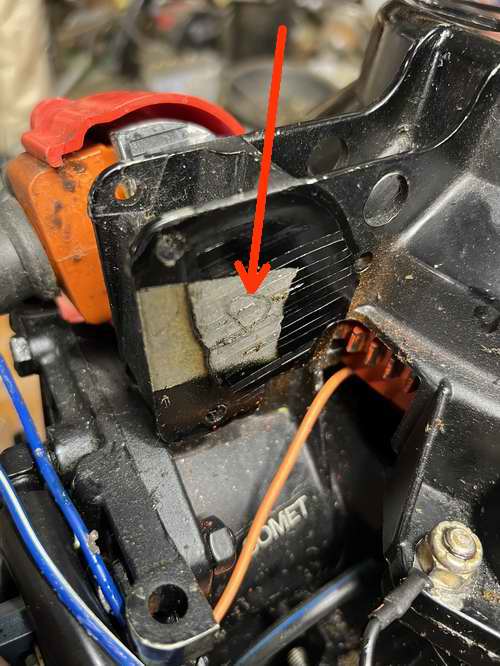
HIGH VOLTAGE IGNITION COILS - The connection to the primary winding of a 7.5hp Merc ignition coil is accessible at the studs on the side of each red coil. This is where the green or blue wires from the CDI module connect, as shown above. The top stud is marked + and the bottom is marked -. This polarity produces the desired negative spark. The secondary winding of the high voltage coil has two conductors; the obvious
one conducts high voltage to the spark plug and the hidden one is the return path from the spark plug screwed
in the block. Without the return path
a spark plug cannot zap. The hidden wire is located at the back of the coil (Fig 1 below), where it is pressed against bare metal to make contact with the aluminum starter bracket. It's worthwhile to expose this connection to clean any corrosion then apply a dab of conductive grease. Conductive grease contains graphite that improves conductivity. It also blocks oxygen, thereby preventing corrosion and is a decent heat conductor to keep the coils cooler. Tighten the 3 brass mounting screws equally to apply uniform pressure against the hidden wires thereby keeping them connected to the starter bracket.
The studs and ring lugs under the rubber caps are now coated with conductive grease. The secondary winding should measure ~1100 Ohms (spark plug lead to block). The primary winding should measure ~.2 Ohms (between + and - terminals). Cont'd below
Cont'd from above. - The coils are mounted on the aluminum starter bracket at the top of the outboard that also support the electric starter motor and the recoil starter. The starter bracket is bolted on top of the power head (engine block) where the spark plugs are screwed in. For this reason the mounting bolts are part of the electrical return path for the high voltage to the spark plugs. The bolts experience vibration and loosen with time. Once loose it creates intermittent spark. Check them occasionally. (A bit simplistic but not everyone understands electricity).
UPDATE IS THE IGNITION COIL POLARITY SENSITIVE? The short answer is NO. The primary winding of the ignition coil on an outboard is not polarity sensitive in a way that reversing the wires from the CDI can prevent it from generating a spark. The basic physics of an induction coil means that any changing current passing through the primary winding (whether positive or negative) can induce a high voltage in the secondary winding. Fact is, the primary winding of an outboard equipped with CDI is usually electrically isolated from ground so any polarity can be applied. BUT, for optimal engine performance and spark plug life, the polarity applied must be such that the secondary winding produces a negative voltage at the spark plug. This spark is several thousand volts more negative than the case ground potential of the outboard. As difficult as this may be to understand, the electron flow is still negative to positive. Of course this applies to Panache's 1976 Mercury 7.5hp outboard. Key Points on Ignition Polarity
Measure Spark Polarity with Analogue Meter - You can test for correct spark polarity by hooking up an analogue voltmeter with the negative lead to the plug terminal (which should be of negative polarity) and the positive lead to the engine block (which should be of positive polarity). Include the diode. Set the meter initially on the highest volt DC range to measure the negative spark as per the diagram below.
|
|||||||||||||||||||||||
|
SPARK PLUGS (2025) - I have operated this 1976 Merc 75 outboard for 40+ years with Bosch spark plugs as they were the ones it was equipped with when I bought Panache. I cleaned them during each annual service but they were looking a bit worse for wear this year. Then in 2025 I discovered they were the wrong plugs for this engine. It would be nice to have the manual. When I learned the correct plugs to be NGK BUHW or Champion L78V "Perma Gap" plugs, I thought it high time to try some. Boy are they difficult to source locally but as luck would have it, I had a set of NGKs deep in the parts box I received from the previous owner. "There is an expression for this, but silence is golden and discretion is the better part of valour." Success, a healthy
whitish spark at both plugs.
A yellow or orange spark is weak. A white or purple spark is strong. And all I needed to do was test the new Ignition Switch Box. TRADITIONAL SPARK PLUG - Having the correct heat range of a spark plug can prevent the ceramic nose from carbon fouling. The heat range is mostly determined by the length of the ceramic nose and to some extent the size of the gap between the ceramic insulator and the metal body of the plug. The final operating temperature has a lot to do with how much heat the plug conducts to the cylinder head. PERMAGAP SPARK PLUG - Permagap (or surface gap) spark plugs are used for high performance, high compression engines (especially 2 stroke) because this design provides a very large consistent spark that resists fouling and pre-ignition better than traditional plugs. However they require a high energy CDI system. They perform poorly at idle with points ignition ignition system, making them unsuitable in an older outboard or street car. They work by the spark jumping from the center electrode
to the metal shell, offering improved flame kernel propagation in a hard running condition. |
|||||||||||||||||||||||
|
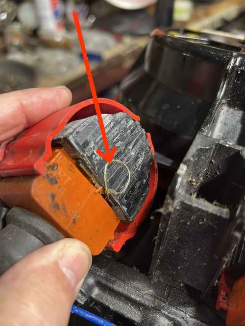
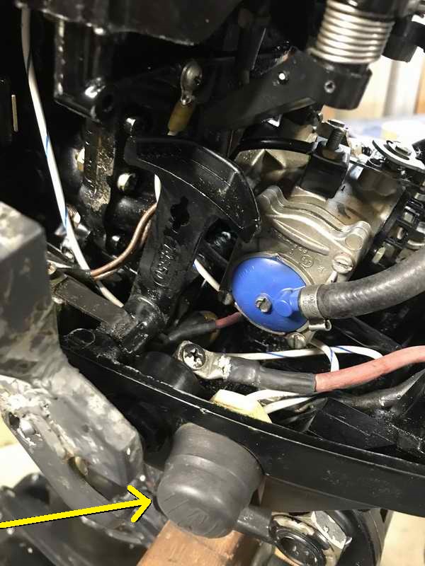
Upon closer examination in the dark areas under the block I discovered the insulation on the kill switch wires was also corroded and brittle. Another problem waiting to jeopardize my adventures. Aaaarch. This switch was also manufacture discontinued and equally expensive to replace. But I was able to refurbish it, saving me ~$80 Ca in exchange for some sweat equity. The kill switch was easy to remove by cutting both wires and spinning off the retaining nut and prying off the neoprene cap. With the switch free of the outboard the remaining wire stubs were cut off immediately behind each hollow contact pin inside the switch. This allowed me to use a narrow punch to drive each pin out of the housing. It helps if you support the connector housing on a matching size socket clamped in a bench vice. Once extracted, the wire end of each pin was filed flat and a depression ground using a Dremel burring bit. This facilitated drilling out the old wire from inside the hollow pin. Since the metal surface of the inside of the pin was whistle clean I inserted a new wire and soldered it in place. The excess solder was filed off the outside of both contact pins so they could slide back inside the connector housing. Next I slipped the neoprene cap over the connector housing and tested the switch for continuity. This switch creates a momentary closure when depressed and held open by the tension of the neoprene cap. The switch assembly was installed in the outboard frame and the new wires directed to their respective terminal. This allowed me to cut the wires to length, crimp and solder a new ring connector to each and tighten the rings under their respective terminal.
Success, the switch can kill the spark again. |
|||||||||||||||||||||||
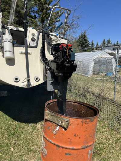 PRESEASON TEST RUN (2025) - Since I needed confirmation that the Merc would run prior to launch, I mounted it on Panache's outboard bracket, using the internal gas tank and my running barrel. I chose this technique because I don't have a second gas tank to perform this test on my engine stand. It was also too early in the season to haul Panache to the launching ramp due to ice on the lake. Besides, that is way too much work for this test. PRESEASON TEST RUN (2025) - Since I needed confirmation that the Merc would run prior to launch, I mounted it on Panache's outboard bracket, using the internal gas tank and my running barrel. I chose this technique because I don't have a second gas tank to perform this test on my engine stand. It was also too early in the season to haul Panache to the launching ramp due to ice on the lake. Besides, that is way too much work for this test. I positioned my run barrel under the outboard, filled it deep enough to immerse the water pump, then hit the starter switch. Voila, it started instantly and purred like a kitten. It took only a couple of minutes to burn off the fogging oil, much quicker than previous years. So I think that things are running better. Standing next to the outboard with it running at eye ball level is a strange sensation. You notice little problems that you can't see looking down from the cockpit. It sure is a lot easier to see a solution for each problem when you can see into the cavities around the block. For instance, the throttle in the full advanced position pushed the generator wire over which would eventually break it. All I had to do was direct the wire to the opposite side of the terminal and it was fixed. Not the easiest to access but... The wires for the kill switch were redirected through a cavity deep behind the block, instead of through the maze of wires the factory directed them through. To "fix" both required surgical removal of two layers of hardware, much like accessing things on a sailboat. Remove 10 things to tighten one screw.
THE DELIVERY RUN - The delivery trip down the lake went absolutely perfect. The engine started instantly with the electric starter and purred like a kitten at idle. It gushed out a steady stream of cooling water. The new spark plugs made only the slightest ignition noise on the VHF radio, sounding a lot like a needle on a dusty LP record; comforting and not at all interfering to speech. As far as operating the kill switch goes, if I don't push and hold the switch till the engine
is totally dead, it will just spring back to life again. Ironic
but annoyingly good. Gawd I love it when things works. |
|||||||||||||||||||||||
|
Return to Tech Tip Index. . . . . . . . . . . . . . . Have a Question? |
|||||||||||||||||||||||