| SJ23 Tech Tip D15, (Updated 2026-04-27) Bob Schimmel. | |||||||||
|
Outboard Repairs - 1976 Merc 7.5hp Running a Tad Rough. |
|||||||||
|
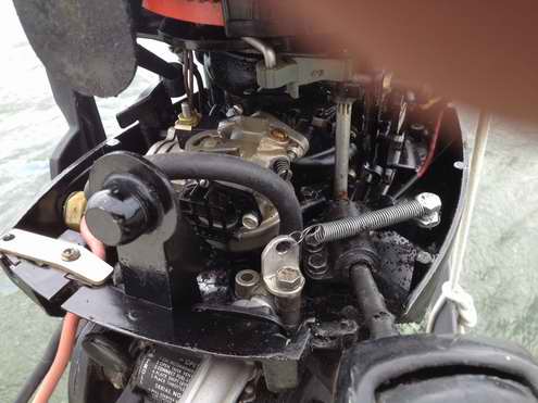
My trusty 7.5HP Merc was idling a little rougher than I liked at the end of this season and not quite as smooth at cruising speed. It starts OK, which is normal, since this engine has electric star, which is a very nice feature by the way. But the rough running has me wondering about the carburetor and the reed valves, power head seals, and the check valve, given the age of the outboard. I might be able to do both jobs at the same time since they are mounted adjacent to each other, sort of. |
|||||||||
|
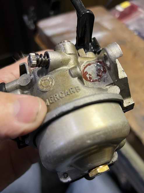
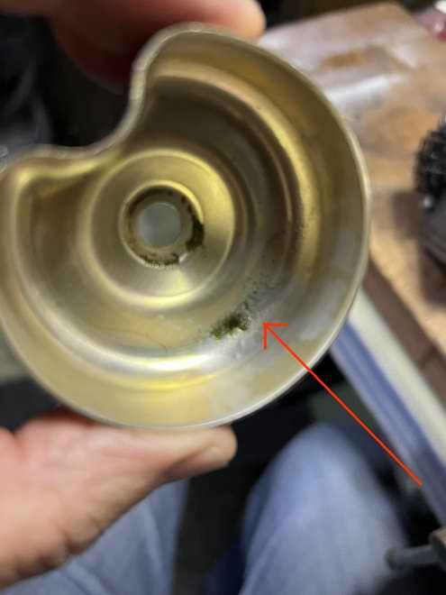
CLEAN CARBURETOR (2025) - Before anything else, check the carburetor body for signs of leakage. Don't destroy the evidence by handling it and take photos as you will question your memory! With the carburetor removed, its wise to plug off the air intake to keep debris out of the engine. Now THAT is guaranteed to tick you off!
|
|||||||||
|
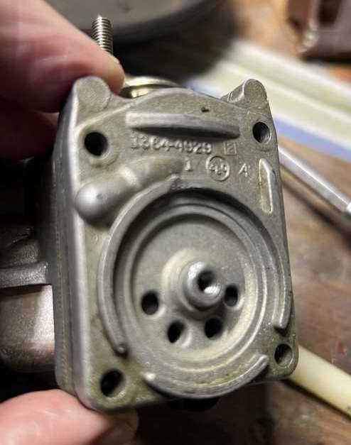
POWER HEAD - The power head holds the vertical crankshaft with pistons, bearings and end seals (top & bottom). The reed valves straddle the middle of the crank shaft. The power head must be air tight for the outboard to function. Some tell tale signs of leaky power head are; rough starting, erratic idling, and poor high speed performance. With all the repairs documented in this tech tip, this engine no longer exhibits these symptoms. It may be possible to test reed valves and end seals while engine assembled by pumping air through the carburetor throat. The reeds will open slightly to let air pass into the crankcase and then they should close to hold ~3-7 PSI pressure when the pump is removed. If you hear air leaking out the carburetor, or if you can't build any pressure in the power head, the reeds or power head end seals are leaking (assuming the rings still seal). The leaks warrants a repair.
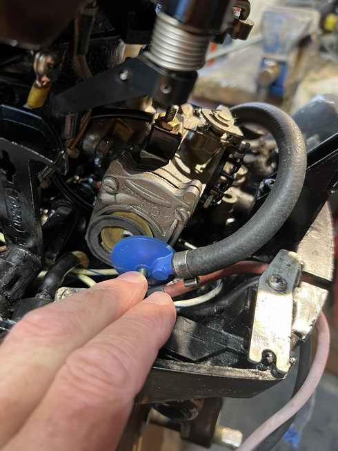
POWER HEAD LOWER BEARING CHECK VALVE (2026) - There is a
tiny brass check valve (elbow) screwed into the bottom outside corner of the power head. Its purpose is to suck accumulated gas and oil from the lower crankcase bearing via an external vacuum tube connected to the top of the intake port. A defective check valve can adversely affect the running of a 7.5HP Merc. In a worse case situation the combustion air is too rich and the engine cannot start. - If this valve is plugged so it can't suck, the engine will be difficult to start due to having too rich fuel mixture. A quick check on a warmish winter day confirmed that Panache's check valve was partially stuck open, defeating the one way air flow by allowing some air to flow freely both ways. So I removed it using a 5/16" open end wrench, 1/8th of a turn at a time. This part was fairly easy despite it being slow as molasses. After a few blasts of carburetor cleaner through the valve I poked inside with a thin wire and it consistently came out clean. No more grunge. Then I gave it a liberal spray of carburetor cleaner to wash away debris that could make the valve stick. I achieved full flow one way through the valve and total block the other way to ensure it worked again. Blowing and sucking confirmed a fix. Now the valve was ready to install and that's when the fun started! After an hour long struggle trying to screw it back in without cross-threading, the magic happened. Fine thread is difficult to start at the best of times. I had to go by feel as I could only get 2 fingers in the narrow gap beside the block. Suffice it to say that its a lot easier to remove than install! Keep the kids away unless you want them learning "garage talk" early in life. The outboard is now tickety-boo and ready for a test run. BARREL TEST (2026) - To test the outboard at home I temporarily removed the last portion of the fuel line from Panache and took home along with my run barrel. I also fabricated a temporary power cable to operate the electric starter from the boat battery. The temporary "gas tank" was a 1L oil bottle propped between bricks on a stool beside the barrel. Goofy I know, but it worked. I'm happy to report the outboard started on the second push of the starter switch, running smooth after I tweaked the idle mixture screw. As expected the engine pushed out a lot of smoke the cleared quickly. It was very responsive. Panache will be good to go for this season. Out on the water it produced hardly any smoke compared to before my maintenance work.
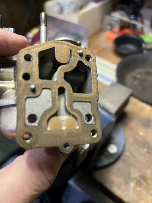
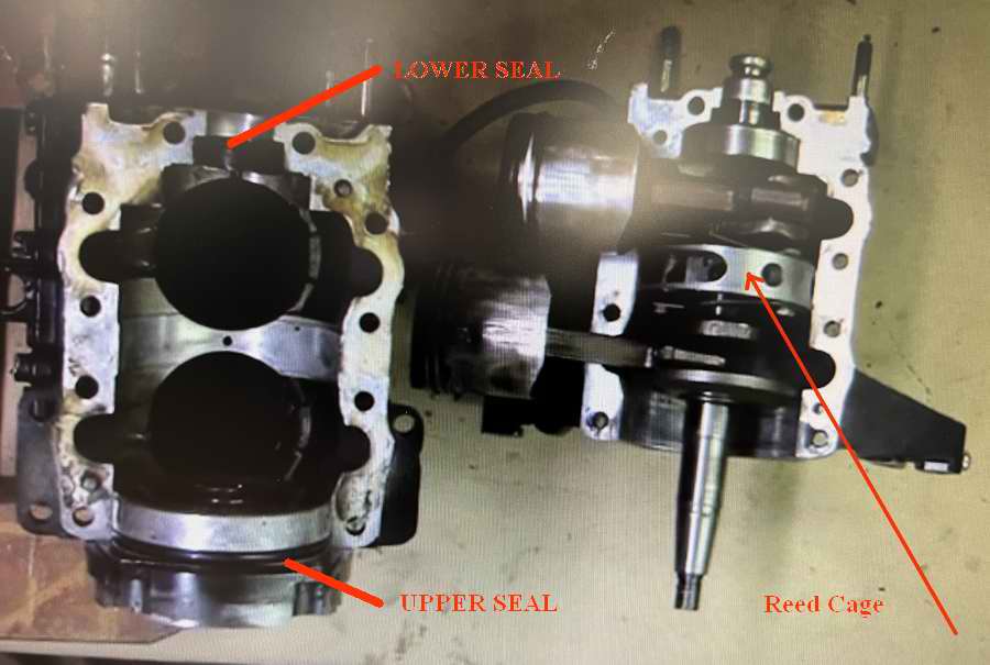
POWER HEAD REED VALVES (future reference) - Reed valves in a 2 cycle outboard are installed directly behind the carburetor. They are essentially a one way air valve to let combustion air in, but NOT out. It is absolutely necessary they close air tight when the piston compresses air on the downward stroke against the closed reeds. As the piston reaches the bottom of its stroke it opens the intake port and all that compressed air in the crankcase rushes into the cylinder for the power stroke. Here is an excellent description of the operation of reed valves. Pay attention to his description of the operation at the end. With time reed valves fatigue (leak) and they no longer close to seal tight. A worse case scenario would be gas droplets expelled from the carburetor, hence the reason why the throat is wet. A reed valve can also stick open, crack or break with similar symptoms. Good reed valves provide quick starting, strong acceleration, smooth power throughout the RPM range with optimum fuel economy for the long distance user. The reed valve cage on many outboards is bolted to the block right behind the carburetor, making it fairly simple to inspect or replace. However, the reed valves on a 1975 Merc 7.5 HP are installed around the middle of the vertical crankshaft (Part 1), and (Part 2) splitting the crankcase into upper and lower chambers. Each chamber has a set of 4 reeds to control air flow. The combustion air is sucked through the carburetor, the front of the power head (intake manifold), then through the side of the round reed valve cage and finally up or down through a set of reed valves into a cylinder crankcase. Its a slick design to be sure but to access the reed cage requires splitting the power head in half (4 Phillips screws down each side of the power head). This exposes the crankshaft with reed cage (8 SS reeds). Splitting the power head also exposes the crankshaft upper (O-ring & spring loaded seal) and the lower (spring loaded seal) that may need to be replaced to seal a leaky power head. Once you have the old reeds out, hold it to the light and you should NOT see an air gap between the tips and the cage. Any sliver of light is a sign of a weak valve and warrants replacing. Carbon fibre or fibreglass reeds generally improve the performance over stainless steel reeds. If one breaks, the loose part shouldn't damage the internal workings of the engine as a part of a SS reed might. Tighten the reed stop screw by hand to prevent over torquing against the cage (.75 ft lbs). Doing so could distort the reeds and the air flow, especially if a reed extends over the edge of the cage. Use a dab of Locktite (blue) on the thread to ensure it doesn't loosen to damage internal engine works.
POWER HEAD END SEALS (future reference) - Prior to ordering parts for this job take note of the top and bottom seals that also seal the power head, making it air tight for efficient combustion. An air leak through any seal in the power head will create a lean mixture, resulting in difficult starting, erratic idling and poor acceleration. PARTS - If you are going to disassemble the power head you should consider ordering the following parts and sealant. - The upper O-ring. ASSEMBLY - Be careful when cleaning the surface of a power head end seal. If you scratch or gouge a surface it creates a potential leak, nullifying all your work. Apply the Permashield sealant and tighten the power head bolts uniformly when assembling. Torque is light, 20-25 in lbs. |
|||||||||
|
Return to Tech Tip Index. . . . . . . . . . . . . . . Have a Question? |
|||||||||