|
 For those of you who ramp launch your boat seasonally wouldn't it be nice to quickly connect the outboard to the boat battery with the cable staying outside the cockpit? To this end I mounted a trailer connector on Panache's transom for the outboard power connection. I've enjoyed this convenience ever since 1981. Its nice to have an uncluttered cockpit. For those of you who ramp launch your boat seasonally wouldn't it be nice to quickly connect the outboard to the boat battery with the cable staying outside the cockpit? To this end I mounted a trailer connector on Panache's transom for the outboard power connection. I've enjoyed this convenience ever since 1981. Its nice to have an uncluttered cockpit.
There are marine connectors designed for this purpose but they are bulky and
ridiculously expensive. And rightly so if you consider the following operational requirements;
water proof, electrical isolation, equipped with a weather proof cap and a strain relief to support the two cables (inside and out). All very necessary. I found the equivalent (almost) in the form of a four pin
automotive trailer
connector at far less cost. The requirements under the back bumper of a
vehicle are not that different from the marine environment.
-
The
metal case of the transom connector is aluminum so no corrosion.
-
The mounting flanges are robust and seal the connector securely to the transom.
-
The spring loaded cap includes a single tooth ratchet to lock the
transom and outboard portions together. Reliability while under way!
-
The transom portion lacks a water tight cap but I solved this with an annual dribble of ATF on the pins to protect them from corroding. The electrical connection has never had a problem to date.
The transom portion is water tight after a generous application of Sikaflex over the cable entry and around the barrel. The outboard portion is water tight with a generous application of Sikaflex over the cable entry and around the barrel. The electrical pins are made of brass. They are big enough to receive the #6 wire and handle
the current demands of the outboard starter. The six
amps of charging current from the generator is minimal in comparison. The connector assembly is polarized so you always plug it in correctly.
 TRANSOM CONNECTOR (Plug) - Its ~12' (3.5 M) from the transom connector to the boat battery installed in the aft end of the starboard settee. To ensure maximum power to the starter I doubled up on the red (positive) and black (negative) wires, with each wire terminated on its own pin in the transom connector. 2 red to the left pins and 2 black to the right pins. At the battery end, the 2 red wires were brought together in a crimped and soldered 2 hole lug, bolted to the primary buss bar. Similarly for the 2 black wires. TRANSOM CONNECTOR (Plug) - Its ~12' (3.5 M) from the transom connector to the boat battery installed in the aft end of the starboard settee. To ensure maximum power to the starter I doubled up on the red (positive) and black (negative) wires, with each wire terminated on its own pin in the transom connector. 2 red to the left pins and 2 black to the right pins. At the battery end, the 2 red wires were brought together in a crimped and soldered 2 hole lug, bolted to the primary buss bar. Similarly for the 2 black wires.
The pins in the transom mounted portion are set in a Bakelite barrel
that is locked to the housing with a tiny set screw. To water proof this I
coated the barrel with Sikaflex, then slid it back into the
connector housing where I tightened the set screw to lock it in place. After that I let the Sikaflex
cure. This connector will likely be impossible to service if maintenance is required
so my solution is to buy another connector since they are relatively
inexpensive. To date I have had no problems with this connection. OUTBOARD CONNECTOR (Jack) - Its only 2' to the outboard with the outboard bracket fully down so no need to double up cables here. However, to ensure maximum power to the electric starter I split the #6 wire strands in 2 bundles, pushing a bundle into each pin. Two adjacent left pins
conduct the positive power and the two adjacent right pins conduct the negative power. Then I coated it all with Sikaflex for insulation and to prevent movement. There is ample power available for the starter and to date I have experienced no problems with this connection. IMPORTANT - Make ABSOLUTELY
certain you have the correct continuity through the transom connection. If you cross
wires on any of the pins you will
have a very dangerous electrical short across the battery. So before you connect to the battery, plug in the outboard connector, and use an ohmmeter to confirm continuity; positive to positive and negative to negative with NO shorts between. Connect the transom cable to the boat battery and confirm the correct polarity at the starter switch in the outboard. If the voltmeter shows positive on the red wire it is safe to push the starter switch to operate the outboard.
INSTALLATION CONSIDERATIONS
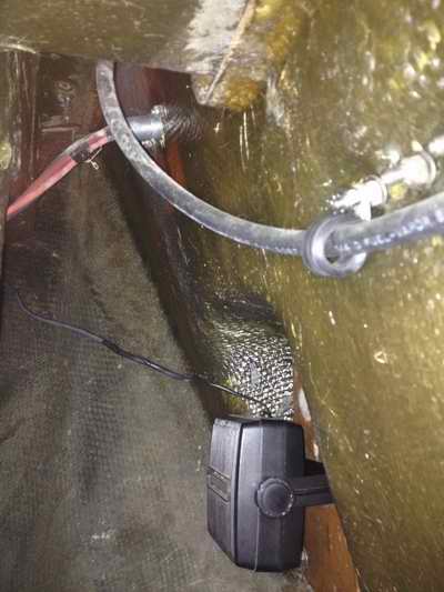
Always support the power cables (especially heavy ones) for their full length. Use a cable tray, conduit, etc. The last thing you want is
a bundle of heavy loose wires swinging with the motion of the hull.
This wears the
insulation away, strains the connector and ultimately invites wire breakage or an electrical short.
Any of these is a recipe for disaster, considering that these
cables are connected directly to the primary buss bars and ultimately to the battery. While it is best to mount power cables high up in
the hull, away from water or loose
stuff stored down low, on an SJ23 there is an unobstructed path along the starboard hull to the battery, from the outboard to the settee. This is the route for the power cable on Panache. To eliminate swinging cables leaving the transom connector I secured the unsupported cable with a tie wrap to the plywood bulkhead at the aft end of the cockpit well. Leave at least a foot of slack in the wires to deal with a future calamity. Its always nice to extract the transom connector out of the hull to service it. The slack can be left coiled on the bottom of the hull. Failing that, more wire can be mechanically spliced to the end or a length spliced in the middle. See table below and don't ask! Remember to use sealed heat shrink or vulcanizing tape wrapped tight over a crimped splice. Follow that with two wraps of electrical tape. It must be air tight and water proof to prevent corrosion. (cont'd below table).
REPAIR WIRES CUT WHILE INSTALLING INSPECTION HATCH (Tech Tip B36)
(How to splice in cold weather)
|
Fig 1 - The surprise I saw when the disk popped out of the transom while installing the inspection hatch. I was not too happy about this. 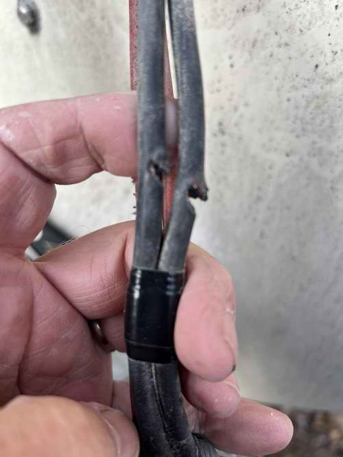
|
Fig 2 - Wires crimped to spec and sealed airtight with Marine Goop. What you see here is the first layer. The second layer made the surface smooth as in 3 below. 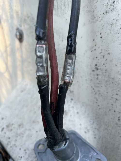
|
Fig 3 - One of two splices insulated with vulcanizing and electrical tape. Both must be stretched as they are wrapped tight. 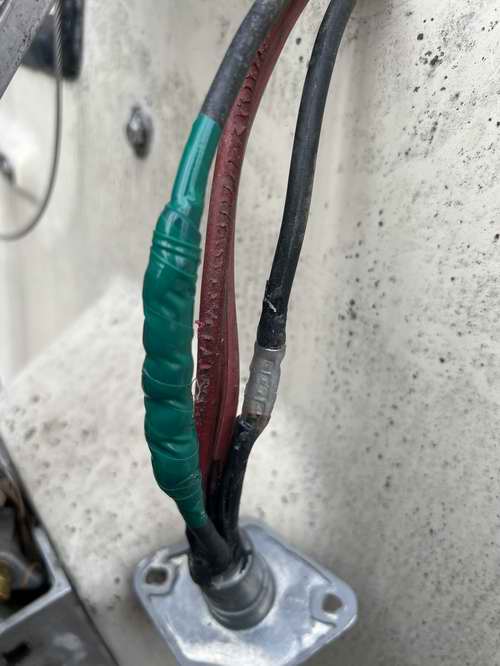
|
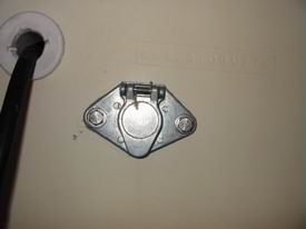
Fig 4 - The outboard connector plugged into the transom connector.
In all the years I've used this, the plug has never slipped out of the jack. 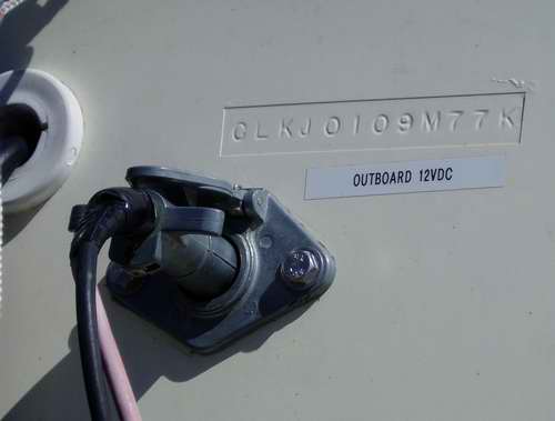
In the Spring I will seal the transom connector to the fibreglass as shown above and secure the unsupported cable to the bulkhead that supports the aft end of cockpit. After this Panache will be good to go again with vibration free power cable. NOTE - Splicing these wires took 4 days due to the short weather windows each day, being so late in the Fall. I had snow on the ground during my last day that demanded keeping the rolls of tape tucked inside my coat. It brought back fond memories of working in the Arctic.
|
Spray the connector pins annually with fogging oil or dribble ATF on the pins to prevent corrosion. This is the trick that converts a
connector from dry use to wet use so it can operate on the water. See Tech Tip E01 for connection to battery. See Tech Tip D13 for electrical connection under outboard cowling.
|